
Archives
now browsing by author
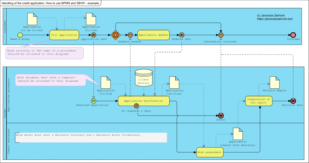
Handling of the credit application. How to use BPMN and SBVR – example.
A common problem in companies, both very small and very large, is the lack of full knowledge of how the company really works. The consequence is the unpredictability of the consequences of decisions taken.
Innym negatywnym efektem tego braku wiedzy jest trudność w zawieraniu umów i wdrażanie do pracy nowych pracowników.
The solution to both of these problems is a correctly executed business model, the backbone of which is business process maps, associated procedures, business rules and document templates. A correctly developed model allows you to familiarise yourself with everything that affects the business quickly. It also allows everyone to understand how the business works.
Below is an example of such a model: the business process model.
Mechanism of Operation vs System Model vs Diagram
Mechanism of Operation vs System Model vs Diagram
Author | Jaroslaw Zelinski |
Date | 2024-03-12 01:48:01 |
Categories | Business analysis and software design |
Introduction
During analysis, we often use the term ‘model’ and less frequently the term ‘mechanism’. The term “mechanism” when we want to explain something, such as “the mechanism for generating a discount on an invoice.” ”
But here beware: the model (block diagrams, formulae, etc.) is documentation and a copyrighted description. The mechanism is what we understand by reading this documentation (model), as the mechanism is protected know-how. The content of the application to the Patent Office is the model (description), but what we patent is the invented/developed mechanism.
Keywords: model, mechanism, diagram, UML
Mechanism vs. model
Mechanism and model in science are close concepts. For example, they are described as:
Modeling involves abstracting from the details and creating an idealization to focus on the essence of a thing. A good model describes only the mechanism. [Glennan argued that mechanisms are the secret connection that Hume sought between cause and effect: “A mechanism of behavior is a complex system that produces that behavior through the interaction of many parts, where the interaction between the parts can be characterized by direct, invariant generalizations relating to change” (Craver & Tabery, 2019)
Let’s examine how these terms are defined by the official Dictionary of the Polish Language:
Mechanism: “the way something is formed, runs, or operates.”
Model: “a construction, scheme, or description showing the operation, structure, features, relationships of some phenomenon or object.” “
Dictionary of the Polish Language (https://sjp.pwn.pl/)
As you can see, very similar but not identical. The term “diagram” is defined in English literature as:
Diagram: a simple plan showing a machine, system, or idea, etc., often drawn to explain how it works.
(https://dictionary.cambridge.org/)
In the scientific (English-language) literature, the concept of modeling is defined as follows: to
model something is to create a copy or description of an action, situation, etc., so that it can be analyzed before proceeding with the real action.
https://www.oxfordlearnersdictionaries.com/definition/english/model_2?q=modeling
Graphically, this conceptual model can be illustrated as a diagram:

Concepts: diagram, model, and mechanism, and the areas of law governing them. (Author’s own)
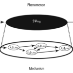
There remains the question of concepts: the phenomenon (which we want to describe and explain) and its explanation. A given phenomenon is a certain observed fact. Most often, we describe it literally or create statistics about it. Craver illustrates the relationship between the phenomenon and the mechanism of its formation in this way:

The upper ellipse represents our observations of stimuli and effects, and the ellipse is a record of the facts and their statistics. Statistics, however, is not a model, it is only a statistic, a collection of data about the facts, it does not provide any explanation for their formation.
The lower ellipse represents the mechanism that explains the formation, initiated by stimuli, of the observed effect (facts collected in statistics). It is an explanation of how the effect (facts, effect) arises and is the mechanism for the emergence of what we observe. We illustrate (can be expressed as) this mechanism (explanation) as a model, which can be expressed, for example, by a flowchart.
Examples
An example that everyone is probably familiar with is Copernicus’ Theory. The diagram shows: top left, a record of observations of the heavens, wrongly called a (statistical) model. These are the so-called epicycles (below left): a depiction of observations of the paths of planets and stars in the sky, observed from Earth. On the right, the heliocentric solar system diagram is a model that explains the mechanism of epicycles or loops that the observed stars and planets make in the sky.

Watt Regulator
Another example is the Watt regulator. Below is a model of this regulator:

The original schematic is Watt’s regulator, describing its design.
The description of the mechanism in the patent application was text similar to this:
If the machine is at rest, then the weights (balls) are at the very bottom, and the throttle is fully open. If the steam machine starts working, the rotating wheel of the steam machine is connected to the speed regulator, the balls begin to rotate. Two forces act on the balls of the regulator: the gravitational force attracting the balls vertically downward and the centrifugal force pulling the balls outward, which, with this design of the regulator, causes the balls to float upward. The rising balls cause the throttle to close, and this resulted in less steam being supplied to the steam engine. The machine slows down, so the centrifugal force decreases, the balls fall down,soandthe throttle opens, thus supplying more steam to the machine.
https://pl.wikipedia.org/wiki/Regulator_od%C5%9Brodkowy_obrot%C3%B3w
Diagram describing this regulator:

Diagram describing the mechanism of the Watt Regulator.
The mechanism that explains the operation of this regulator is a negative feedback system (Bertalanffy, 2003):

Negative feedback as a mechanism to explain the operation of the Watt regulator.
Watt’s regulator is precisely the negative feedback. In the diagram above, PROCESS is a steam machine. The quantity at the input is steam with a certain pressure, and the quantity at the output is the speed of the drive shaft of the steam machine. An increase in the speed of the shaft causes a decrease in the pressure of the steam supplying the steam machine, which in turn causes a decrease in the speed of the shaft, thus opening the steam valve at the input and increasing the speed again. The phenomenon will lead to a fixed (stabilized) shaft speed with small fluctuations.
Clock
A typical analog clock (its face) hanging on many walls in a house (or mounted on many towers) looks like the one below:

Clock face
Possible construction of such a clock on the tower:

Example of a design reproducing a clock mechanism
The time measurement mechanism we use to explain the indication on the clock face, which is the basis for the construction of clocks, is expressed as a model in UML notation.

A model expressing the timing mechanism
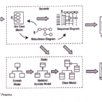
Conceptual model.
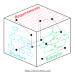
We model domain knowledge as a Concept Dictionary, and this can be expressed graphically in the form of taxonomies and syntactic relationships. The application code architecture expressed graphically is its model, adding to fewer diagrams describing♥ for example, use case scenarios, is also part of this model. The whole, however, describes the mechanism for implementing functional requirements.
Below left conceptual model, he ne is, however, the mechanism for the implementation of functional requirements. On the right, the model (fragment) of the application architecture, supplemented with a sequence diagram, would be a model describing the mechanism of implementation of a specific functionality.

Summary
As you can see, sometimes it is easy to confuse the terms model and mechanism, but we can say that a model is a diagram depicting something, while a mechanism is an explanation of a phenomenon (how something is created how it works). A mechanism can be illustrated in the form of a model. If we aim for the model to be an idealization, then that’s it:
Modeling involves abstracting from the details and creating an idealization so as to focus on the essence of a thing. A good model only describes the mechanism.(Craver & Tabery, 2019).
Bertalanffy, L. (2003). General system theory: foundations, development, applications (Rev. ed., 14th paperback print). Braziller.
Craver, C. F. (2007). Explaining the brain: mechanisms and the mosaic unity of neuroscience. Clarendon Press.
Craver, C., & Tabery, J. (2019). Mechanisms in Science. In E. N. Zalta (Ed.), The Stanford Encyclopedia of Philosophy (Summer 2019). Metaphysics Research Lab, Stanford University. https://plato.stanford.edu/entries/science-mechanisms/
Frigg, R., & Hartmann, S. (2020). Models in Science. In E. N. Zalta (Ed.), The Stanford Encyclopedia of Philosophy (Spring 2020). Metaphysics Research Lab, Stanford University. https://plato.stanford.edu/archives/spr2020/entries/models-science/
Weilkiens, T. (2007). Systems engineering with SysML/UML: Modeling, analysis, design (1. Aufl). Morgan Kaufmann OMG Press/Elsevier.
System design and implementation
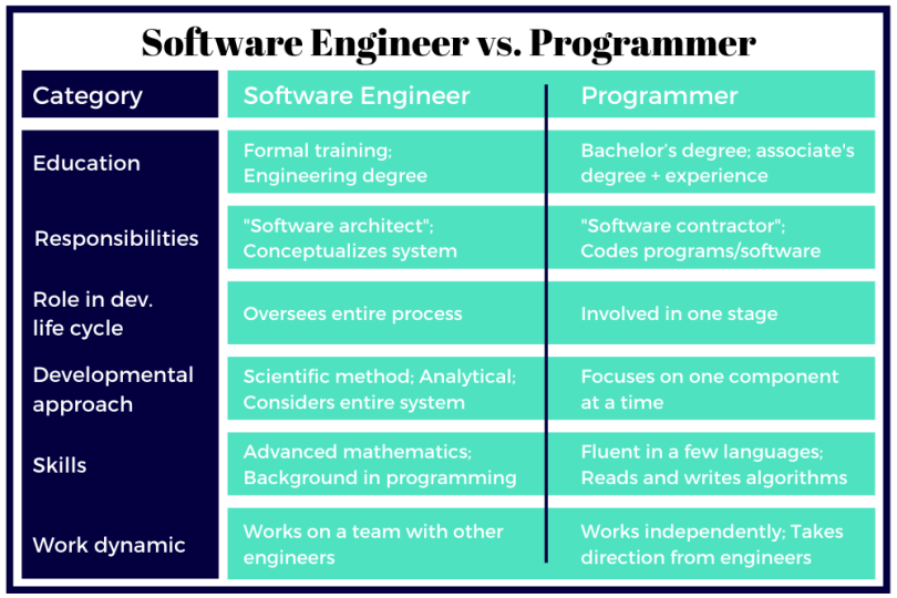
WHAT DOES A SOFTWARE ENGINEER DO?
Software engineers evaluate client or company needs in conjunction with those of the user and methodically conceptualize a systematic solution (also System Engineer).
This person is a Solution Designer…
WHAT DOES A PROGRAMMER DO?
Programmers write code and debug errors in programs and software based on instructions from software engineers. They are involved in a single stage within the development lifecycle and concentrate on one component at a time (also System Developer).
Design and implementation process
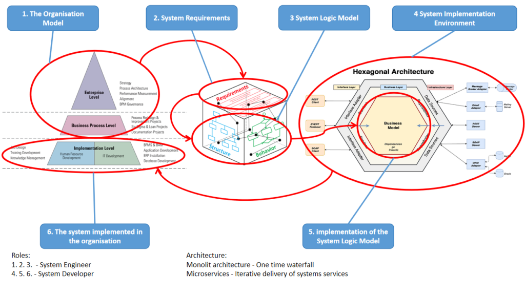
How it works for those who succeed:
- an organisational model is created (business processes and document structures)
- define business requirements (needs)
- a platform-independent logic is designed to implement the requirements (system model)
A developer is then selected to:
- selects and sets up the environment
- implements the designed logic in the selected environment
- deliver the system to the users and implement it.
NOTE!
- If the project is monolithic, the implementation will be a “big risky waterfall”.
- If the project is a component architecture (microservices), the implementation will be a smooth, iterative and incremental process (points 5. and 6. in the loop).
I’m System Engineer…
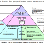
Above diagrams from the left (Bibliography):
Paul Harmon. (2016). The State of Business Process Management 2016. BT Trends. https://www.club-bpm.com/Contenido/Estudios/BPT-Survey-Report.pdf
Bajaj, M., Cole, B., & Zwemer, D. (2016, September 13). Architecture To Geometry—Integrating System Models With Mechanical Design. AIAA SPACE 2016. AIAA SPACE 2016, Long Beach, California. https://doi.org/10.2514/6.2016-5470
Cockburn, A. (2005, January 4). Hexagonal architecture. Alistair Cockburn. https://alistair.cockburn.us/hexagonal-architecture/
A good beginning and then it gets worse, i.e. MVP
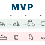
Why problems occur” only later”, at the beginning it was good and the customer was satisfied
Paradoxically, the explanation is quite simple: developers are still dominated by methods based on monolithic architectures. Preaching application” Object-oriented programming methods” only means that the so-called” object-oriented programming language”, which absolutely does not mean that the architecture of what will be created will be modern. Audit practice shows that it will rather be an architectural museum based on a relational data model, multi-level inheritance and the worst data modeling practices, which are an anemic domain model and shallow flat classes with a huge number of operations (including set/get for each attribute of classes representing database tables).
Therefore, this scenario often looks like this: at the beginning, software is created that performs one specific function, often the embryo of a monolith. Everything works fine, the customer is happy and concludes (extends) the contract. The next functionalities are the beginning of the drama: expansion of the monolithic data model, migrations from the old model to the new one, growing problems of the monolithic architecture: everything is falling apart because everything depends on everything, and no one knows how, because there is no documentation of the application’s operation mechanism, and the code has long been no longer suitable for reading. Trying to fix this is starting to be a bit of a rabbit chase too…. and there is a dispute.
Source: A good beginning and then it gets worse, i.e. MVP – IT-Consulting Jarosław Żeliński
Mechanism of operation vs. system model
Most often in the course of analysis we use the term model, less often mechanism. The thing is that the term mechanism appears when we want to explain something, e.g. “the mechanism of generating a discount on an invoice”. The thing is that the term mechanism appears when we want to explain something, e.g. “the mechanism for generating a discount on an invoice”. But here beware! A model (block diagrams, formulae, etc.) is documentation, a copyrighted description. The mechanism is what we understood by reading these documentation (model), because the mechanism is protected know-how. The content of the application to the Patent Office is the model (description), but what we patent is the mechanism invented/developed.
Source: Mechanism of operation vs. system model – Jarosław Żeliński IT-Consulting
Architecture & Systems Engineering
I highly recommend the MIT Architecture & Systems Engineering course. it is precious knowledge and an increasingly popular skill: the analysis and design of complex, interdisciplinary systems.
Enroll in MIT’s Architecture & Systems Engineering Online Program and learn from MIT faculty and industry experts. Explore the newest practices in systems engineering, including how models can enhance system engineering functions and how systems engineering tasks can be augmented with quantitative analysis.
Source: Enroll in MIT’s Architecture & Systems Engineering Online Program
If you are looking for local personal mentoring, I am an experienced MBSE expert, please ask for details.
Enterprise Architecture – goals and scope of analysis and modeling
Enterprise Architecture – goals and scope of analyzes and modelingPurpose and benefitsThe primary goal of analyzing and modeling the entire company, at a predetermined level of detail (or rather the level of generality), is to determine the context for specific local, domain-specific projects. The whole model contains information about the document flow and the IT systems supporting it. The key benefit of having a documented Enterprise Architecture is an even several-fold reduction in the costs of ongoing management and development of the IT system, The key benefit of having a documented Enterprise Architecture is even a several-fold reduction in the costs of current company management and the costs of IT system development. Given models we have:possibility to make organizational decisions immediately and without risk: documented information about mechanism of the operation of each business service (business processes), means the ability to perform immediate analysis the impact of each such decision on the rest of the companythe ability to immediately make decisions about introducing necessary changes to the IT system, documented information about the operation mechanism and architecture of the IT system, allows for immediate implementation of the specification“to-be” of this system, and send it to suppliers as a requirement (no need to do any pre-implementation analyses),possibility of implementing business continuity management,possibility of implementing a controlling and activity-based cost management system (ABC method of cost management). See also Target operating model (TOM).
Source: Enterprise Architecture – goals and scope of analyzes and modeling – Jarosław Żeliński IT-Consulting
What is the difference between the requirements of the solution and the needs of the user?
Seven years ago (2015), I ended an article about requirements and traceability with the words: So the business requirements may be dozens. The required system services (use cases) in a large project may also be dozens. But hundreds or thousands of ?requirements? is an expression of losing control of the project scope? Here I would like to point out that a requirement (a system service) could be, for example, a VAT invoice produced in compliance with the regulations. The features of this invoice (list of fields) are not separate requirements, they are features (parameters, attributes) of a single requirement. No feature of the VAT invoice has any value on its own so it cannot be a separate use case, just as our requirement can be a car but its colour or automatic transmission are features of the car, it makes no sense to require ?red colour? without expecting a car (and how to justify that this colour supports the business objective). The use case for a car is the journey and not the insertion of the key into the ignition, because this is just one element of the scenario of starting a car journey.Source: Why is requirements tracing important in a project? – Jarosław Żeliński IT-ConsultingThere are publications about requirements, their management and implementation. There are applications available on the market to collect them and manage such a collection. And we are constantly confronted with their – requirements – ambiguity (Šenkýř & Kroha, 2019). It turns out that their importance becomes crucial for projects, also from a legal perspective (PZP and the concept of need defined in the recommendations of the Public Procurement Office). This time I will focus on the concepts of ‘requirement’ and ‘need’ in relation to the solution design.
Work vs. design vs. intellectual property in engineering
Another discussion I had on LinkedIn recently showed that intellectual property law is very difficult to assimilate, mainly because – due to its ‘immateriality’ – it escapes the intuitive and material manners of human perception of the world. This is overlaid by the coder’s conviction that, in principle, they are autonomous creators, and unfortunately, many lawyers also think so. The thing is that the coder is always the creator, but not always the designer. When the coder is not a designer, their works (source code) are dependent works on primary works, which are technical designs expressed, for example with the help of UML, mathematical formulae, algorithms. Then we expect coders, as developers, to do their craft brilliantly.Given that I often use purposeful and systemic interpretation of contracts and law in the expert reports I write, I have decided to describe here an ontological analysis of this area of engineering. The aim is to determine the meaning and range of definitions of terms commonly used in the field of intellectual property. I also hope to help you with this to make better software supply contracts.
Source: Creation vs. design vs. intellectual property in engineering – Jarosław Żeliński IT-Consulting.
ICONIX as an object-oriented, agile software design process using UML notation
The fact that ICONIX, as a process, is relatively rarely used (this has been changing over the last few years, however), is rooted in the fact that, first and foremost, it requires an understanding of the component-oriented architecture process, it also requires knowledge and understanding of the concept of hexagonal architecture and the associated MVC pattern. Requires knowledge and understanding of many other object-oriented design patterns, requires, above all, abstract thinking and modelling (UML) skills. It requires an understanding that z coding must be preceded by design, because ‘designing’ in code is the least effective form of design (Börger, 2018).The process is also supported by the division into analysis and design and implementation stages (see above diagram: Structure of project roles and products in the ICONIX process). ICONIX is sometimes wrongly associated with a “heavy” software development process such as the Rational Unified Process (which I have hardly written about on my blog). The reason ICONIX is rarely used, is also that, unfortunately, the world was, already in the 1990s, heavily “spoiled” by C++ and Java (architectures built on cascades of inheritance). These are often heavy, monolithic frameworks based on a relational data model, where there is no strict separation between domain logic and environment (MVC). Java is still one of the most costly and least effective application development methods. The EJB framework is to this day described as the source of an object-oriented design anti-pattern called the ‘anemic domain model’. However, the growing developer interest in the C4 model over the last few years shows that analysis and modelling are needed and quietly entering through the back door….The fact that ICONIX, as a process, is relatively rarely used (this has been changing over the last few years, however), is rooted in the fact that, first and foremost, it requires an understanding of the component-oriented architecture process, it also requires knowledge and understanding of the concept of hexagonal architecture and the associated MVC pattern. Requires knowledge and understanding of many other object-oriented design patterns, requires, above all, abstract thinking and modelling (UML) skills. It requires an understanding that z coding must be preceded by design, because ‘designing’ in code is the least effective form of design (Börger, 2018).The process is also supported by the division into analysis and design and implementation stages (see above diagram: Structure of project roles and products in the ICONIX process). ICONIX is sometimes wrongly associated with a “heavy” software development process such as the Rational Unified Process (which I have hardly written about on my blog). The reason ICONIX is rarely used, is also that, unfortunately, the world was, already in the 1990s, heavily “spoiled” by C++ and Java (architectures built on cascades of inheritance). These are often heavy, monolithic frameworks based on a relational data model, where there is no strict separation between domain logic and environment (MVC). Java is still one of the most costly and least effective application development methods. The EJB framework is to this day described as the source of an object-oriented design anti-pattern called the ‘anemic domain model’. However, the growing developer interest in the C4 model over the last few years shows that analysis and modelling are needed and quietly entering through the back door….
Source: ICONIX jako obiektowo zorientowany, zwinny proces projektowania oprogramowania z użyciem notacji UML – Jarosław Żeliński IT-Consulting