
OOAD
now browsing by tag
Mechanism of operation vs. system model
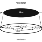
Most often in the course of analysis we use the term model, less often mechanism. The thing is that the term mechanism appears when we want to explain something, e.g. “the mechanism of generating a discount on an invoice”. The thing is that the term mechanism appears when we want to explain something, e.g. “the mechanism for generating a discount on an invoice”. But here beware! A model (block diagrams, formulae, etc.) is documentation, a copyrighted description. The mechanism is what we understood by reading these documentation (model), because the mechanism is protected know-how. The content of the application to the Patent Office is the model (description), but what we patent is the mechanism invented/developed.
Source: Mechanism of operation vs. system model – Jarosław Żeliński IT-Consulting
ICONIX as an object-oriented, agile software design process using UML notation
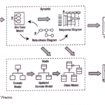
The fact that ICONIX, as a process, is relatively rarely used (this has been changing over the last few years, however), is rooted in the fact that, first and foremost, it requires an understanding of the component-oriented architecture process, it also requires knowledge and understanding of the concept of hexagonal architecture and the associated MVC pattern. Requires knowledge and understanding of many other object-oriented design patterns, requires, above all, abstract thinking and modelling (UML) skills. It requires an understanding that z coding must be preceded by design, because ‘designing’ in code is the least effective form of design (Börger, 2018).The process is also supported by the division into analysis and design and implementation stages (see above diagram: Structure of project roles and products in the ICONIX process). ICONIX is sometimes wrongly associated with a “heavy” software development process such as the Rational Unified Process (which I have hardly written about on my blog). The reason ICONIX is rarely used, is also that, unfortunately, the world was, already in the 1990s, heavily “spoiled” by C++ and Java (architectures built on cascades of inheritance). These are often heavy, monolithic frameworks based on a relational data model, where there is no strict separation between domain logic and environment (MVC). Java is still one of the most costly and least effective application development methods. The EJB framework is to this day described as the source of an object-oriented design anti-pattern called the ‘anemic domain model’. However, the growing developer interest in the C4 model over the last few years shows that analysis and modelling are needed and quietly entering through the back door….The fact that ICONIX, as a process, is relatively rarely used (this has been changing over the last few years, however), is rooted in the fact that, first and foremost, it requires an understanding of the component-oriented architecture process, it also requires knowledge and understanding of the concept of hexagonal architecture and the associated MVC pattern. Requires knowledge and understanding of many other object-oriented design patterns, requires, above all, abstract thinking and modelling (UML) skills. It requires an understanding that z coding must be preceded by design, because ‘designing’ in code is the least effective form of design (Börger, 2018).The process is also supported by the division into analysis and design and implementation stages (see above diagram: Structure of project roles and products in the ICONIX process). ICONIX is sometimes wrongly associated with a “heavy” software development process such as the Rational Unified Process (which I have hardly written about on my blog). The reason ICONIX is rarely used, is also that, unfortunately, the world was, already in the 1990s, heavily “spoiled” by C++ and Java (architectures built on cascades of inheritance). These are often heavy, monolithic frameworks based on a relational data model, where there is no strict separation between domain logic and environment (MVC). Java is still one of the most costly and least effective application development methods. The EJB framework is to this day described as the source of an object-oriented design anti-pattern called the ‘anemic domain model’. However, the growing developer interest in the C4 model over the last few years shows that analysis and modelling are needed and quietly entering through the back door….
Source: ICONIX jako obiektowo zorientowany, zwinny proces projektowania oprogramowania z użyciem notacji UML – Jarosław Żeliński IT-Consulting
Synthesis of MOF, MDA, PIM, MVC, and BCE Notations and Patterns

Exactly one year ago my first paper in US ? (see liflet)
Abstract
Publications, including academic handbooks, contain numerous inconsistencies in the descriptions of applications of architectural methods and patterns hidden under the abbreviations such as MOF, MDA, PIM, MVC, BCE. An efficient analysis and the following software design, particularly when we are speaking of projects realized in large teams, requires standardization of the production process and the applied patterns and frameworks. This study attempted to sort out the system of notations describing this process and used to describe architectural patterns. Analysis of key notations?MOF and MDA, patterns MVC and BCE?was carried out, and a consistent system combining them into a whole was created.Chapter Preview Top
Background
In this study, Object Management Group notation systems have been used. MOF (Meta Object Facility) specification describes three abstraction levels: M1, M2, M3 and level M0 that is real items (OMG MOF, 2016). M0 is a real system, M1 level is abstraction of the items of this system (its model). Level M2 comprises of relationships between classes of these objects (names of their sets) that is system metamodel. M3 level is a meta-metamodel describing the modeling method with the use of named elements with specified semantics and syntactic.
The analysis and design process is based on the MDA (Model Driven Architecture) specifications. This process has three phases understood as creation of subsequent models: CIM (Computation Independent Model), PIM (Platform Independent Model), PSM (Platform Specific Model) and code creation phase. The CIM model is documented with the use of BPMN (Business Process Model and Notation) (OMG BPMN, 2013) and SBVR notation (Semantic of Business Vocabulary and Rules) (OMG SBVR, 2017). These are, respectively: business process models and notation models and business rules. PIM and PSM models are documented with the use of UML notation (Unified Modeling Language) (OMG UML, 2017).
Between CIM and PIM models, determination of the list of application services (system reactions) occurs, whose realization mechanism is described by PIM model. The standard pattern used for modeling application architecture is MVC pattern. Component Model of this pattern is modeled with the use of the BCE architectural pattern.
Semiotics vs. UML
Semiotics, as a science dealing with symbols and their meanings, provides us with the tool enabling determination of relationships between an object (thing), its name (expression) and definition of notation represented by the name (or sign, meaning). These relationships are referred to as the semiotic triangle. Figure 1 represents this triangle on the left (OMG SBVR, 2017).
The UML notation (OMG UML, 2017) operates instance classifier and class notations. To the right, Figure 1 demonstrates an equivalent to semiotic triangle expressed with those terms.
The UML notation further operates the general structure notation, which is the content of each correct UML diagram. Structures may express a conceptual model (Namespace) or model (also metamodel) of system architecture (e.g. software) in the form of a chart (Architecture).
Synthesis of MOF, MDA, PIM, MVC, and BCE Notations and Patterns

Jaroslaw Zelinski (Independent Researcher)
Source Title: Applications and Approaches to Object-Oriented Software Design: Emerging Research and OpportunitiesCopyright: ? 2020 |Pages: 12DOI: 10.4018/978-1-7998-2142-7.ch003