Models and architecture
now browsing by category
The main category of my posts, my experience and research as well.
Thinking in code is harmful

Writing code involves logic, syntax, and execution flow. A developer thinks about loops, variables, and functions to solve a specific, isolated task. The code either works or it does not. System design operates at a higher elevation. It looks at the software as a collection of components that must interact with each other. When a senior engineer looks at a feature request, they do not immediately open a code editor. They pause to look at the data flow. They ask how information moves from the user to the server and finally to the database. They consider what happens if the network is slow or if a hard drive fails. This mental shift requires letting go of the desire for immediate implementation. It requires thinking about the shape of the system before worrying about the implementation details. (The Shift from Syntax to Structure).
Code thinking: the mental process of translating problems into logical instructions for a computer, becomes a weakness primarily when it is applied inappropriately, excessively, or prematurely. While essential for building software, this mindset can lead to over-engineering, analysis paralysis, and a disconnect from the actual user’s needs or business value.
Here is why “code thinking” can be a weakness, based on common pitfalls and expert insights:
- Premature Optimization and Complexity: Code thinking often focuses on how to make a solution efficient, rather than simply making it work. This leads to over-engineering, building complex, “clever” solutions for problems that haven’t happened yet, rather than simple, immediate solutions.
- Analysis Paralysis (Overthinking): Beginners often get stuck in a cycle of excessive research, fearing failure or trying to find the “perfect” plan, which prevents them from actually starting to code. This fear of making mistakes often stems from over-analyzing the steps before taking action.
- Loss of Human Perspective: A “programmer” mindset can focus too much on logic, syntax, and abstract algorithmic efficiency, neglecting the user experience, business value, or the messy reality of user needs.
- Ignoring Existing Solutions: Code thinkers often try to build everything from scratch to ensure it’s “right,” which leads to reinventing the wheel and creating technical debt instead of using existing, tested libraries.
- “Perfect Code” Syndrome: An obsession with clean, perfect code can lead to wasting time on trivial details rather than prioritizing functional code that solves the core problem. This can result in slow progress and an inability to deliver on time.
- Mental Exhaustion: The intense, relentless focus required for programming can lead to mental fatigue. Because code thinking doesn’t allow for much downtime, it can result in decreased performance and burnout.
How to Overcome This Weakness:
- Plan with Pen and Paper: Before writing code, break down problems into smaller parts and solve them mentally or on paper first.
- Embrace Mistakes: Accept that your first attempt will be imperfect. Debugging and fixing errors is a natural part of the learning process.
- Focus on Value over Complexity: Prioritize simple solutions that provide immediate value to the user.
- Take Breaks: Regularly step away from the screen to maintain creativity and avoid burnout.
It is now standard practice to use UML notation for design work prior to coding.
One of the most effective ways to improve your programming logic is to practice visualizing exactly how the computer will execute your code.Bibliography:
- https://algocademy.com/blog/why-your-logical-thinking-breaks-down-when-coding/
- https://designgurus.substack.com/p/beyond-coding-how-senior-engineers
- Baruzzo, A., & Comini, M. (2008). A Methodology for UML Models. 2008 International Conference on Software Testing, Verification, and Validation, 513–516. https://doi.org/10.1109/ICST.2008.66
- Larman, C. (2005). Applying UML and patterns: An introduction to object-oriented analysis and design and iterative development (3rd ed). Prentice Hall PTR, c2005.
- Zhang, Y., Yan, C., Li, Y., & Wang, W. (2020). Design of Fault Diagnosis System for Steam Turbine Based on UML. 2020 11th International Conference on Prognostics and System Health Management (PHM-2020 Jinan), 254–260. https://doi.org/10.1109/PHM-Jinan48558.2020.00052
- Gomaa, H. (2005). Designing Software Product Lines with UML. 29th Annual IEEE/NASA Software Engineering Workshop – Tutorial Notes (SEW’05), 160–216. https://doi.org/10.1109/SEW.2005.5
- Constantinou, A., & Perez, D. (2019). Developing a UML extension for the GUI. 47.
- Zelinski, J. (2021). Digital documents as data carriers and a method of data management guaranteeing the unambiguity of the recorded information. In Management and Strategies for Digital Enterprise Transformation (Vol. 1). IGI Global. https://www.igi-global.com/chapter/digital-documents-as-data-carriers-and-a-method-of-data-management-guaranteeing-the-unambiguity-of-the-recorded-information/275700
- Romanenko, E., Calvanese, D., & Guizzardi, G. (2024). Evaluating quality of ontology-driven conceptual models abstractions. Data & Knowledge Engineering, 102342. https://doi.org/10.1016/j.datak.2024.102342
- Rademacher, F. (2017). Formalizing Domain-driven Microservice Design with UML’s Profile Mechanism. https://www.conf-micro.services/2017/papers/Rademacher.pdf
- Łabiak, G., & Bazydło, G. (2018). Model driven architecture approach to logic controller design. 080003. https://doi.org/10.1063/1.5079137
- Topper, J. S., & Horner, N. C. (2013). Model-Based Systems Engineering in Support of Complex Systems Development. JOHNS HOPKINS APL TECHNICAL DIGEST, 32(1).
- Rauf, I., Ruokonen, A., Systä, T., & Porres, I. (2010). Modeling a composite RESTful web service with UML. Proceedings of the Fourth European Conference on Software Architecture Companion Volume – ECSA ’10, 253. https://doi.org/10.1145/1842752.1842801
- Grover, V., & Kumar, J. (2019). Slicing based on UML Diagram and Test Case Generation. International Journal of Computer Sciences and Engineering, 7(9), 95–101. https://doi.org/10.26438/ijcse/v7i9.95101
- Zelinski, J. (2020). Synthesis of MOF, MDA, PIM, MVC, and BCE Notations and Patterns. In Applications and Approaches to Object-Oriented Software Design: Emerging Research and Opportunities (pp. 78–89). IGI Global. https://www.igi-global.com/book/applications-approaches-object-oriented-software/235699
- Rademacher, F., Sachweh, S., & Zündorf, A. (2018). Towards a UML Profile for Domain-Driven Design of Microservice Architectures. In A. Cerone & M. Roveri (Eds), Software Engineering and Formal Methods (Vol. 10729, pp. 230–245). Springer International Publishing. https://doi.org/10.1007/978-3-319-74781-1_17
- Robert C. Martin. (2003). UML for Java programmers. Prentice Hall PTR.
- Robert C. Martin (with Grenning, J., & Brown, S.). (2018). Clean Architecture: A craftsman’s guide to software structure and design. Prentice Hall. https://raw.githubusercontent.com/sdcuike/Clean-Code-Collection-Books/master/Clean%20Architecture%20A%20Craftsman’s%20Guide%20to%20Software%20Structure%20and%20Design.pdf
- Pérez-Castillo, R., & Piattini, M. (2022). Design of classical-quantum systems with UML. Computing. https://doi.org/10.1007/s00607-022-01091-4
- Garland, J., & Anthony, R. (2003). Large-scale software architecture: A practical guide using UML. J. Wiley. https://largescalesoftwarearchitecture.com/
Computerisation as an ontological project
Wprowadzenie

Modern organisations invest heavily in digitalisation, expecting IT systems to streamline processes, boost efficiency and enable better decision-making. The paradox, however, is that many of these projects end in disappointment: the systems fail to support the business, processes become rigid, and the organisation loses control over its own knowledge. The cause is not the technology, but a fundamental misunderstanding of the nature of organisational digitalisation projects.
Contrary to popular belief, digitalisation is not a programming endeavour. It is an ontological project, involving the modelling of an organisation’s reality, its concepts, relationships, principles and decision-making processes. Only on this basis can software be developed. Unfortunately, in practice, the order is reversed: it is developers – rather than analysts, knowledge architects and systems designers – who are responsible for defining the organisation’s semantics. It is worth noting here that numbers currently account for only a small fraction of the content being processed.
Ontology as the foundation of information systems

Every IT system is a concrete manifestation of a certain view of the world (see Plato’s Cave). It contains answers to the following questions:
– what constitutes a customer, a product, an order, a case, a document,
– what relationships between these entities are permissible,
– what rules govern their processing,
– what decisions can be made and on what basis?
These are not technical issues. They are matters relating to ontology, epistemology and knowledge management. An IT system is therefore nothing more than a formal model of an organisation, encoded in data structures, processes, rules and interactions. If the model is flawed, incomplete or haphazard, so too will the system be.
Why developers should not design organisational ontologies
Developers are experts in implementation, optimisation, integration and technical architecture. However, they are not – nor do they need to be – specialists in business semantics or conceptual modelling. Expecting a programmer to design an organisation’s ontology is like expecting a bricklayer to design a cathedral. A developer will build the walls, but will not design the house.
As a result, systems are created that reflect not the reality of the organisation, but the developer’s interpretation – often formed under the pressure of sprints, backlogs and time constraints. Data models are haphazard, processes are oversimplified, and business logic is hard-coded, making it impossible to understand or evolve.
Consequences: loss of control over the organisation’s knowledge
When an ontology isn’t deliberately designed, the organisation loses control over it. After a few years, nobody knows:
– why the system works the way it does,
– where the rules came from,
– how to change the process without rewriting half the application.
The system becomes a black box, and every change costs more and more. In extreme cases, the organisation starts to adapt to the system – rather than the other way round.
Model-Based Systems Engineering as an antidote
The solution is to return to principles that are self-evident in other fields of engineering: model first, implementation second. In practice, this means creating:
– a domain ontology,
– a conceptual model,
– a process model,
– a decision model,
– an information model,
– an interaction model.
Only on this basis can the logical and technical architecture and the implementation be designed. This is the essence of Model-Based Systems Engineering (MBSE) – an approach that enables organisations to regain control over their own knowledge and ensures consistency between reality and systems.Dopiero na tej podstawie można projektować architekturę logiczną, techniczną i implementację. To właśnie esencja Model-Based Systems Engineering (MBSE) – podejścia, które pozwala organizacjom odzyskać kontrolę nad własną wiedzą i zapewnia spójność między rzeczywistością a systemami.
The question that changes the conversation with the board
When working with management teams and clients, one question often proves crucial:
Do you want the system to reflect your organisation, or the developer’s interpretation?
This question gets to the heart of the matter and highlights the fact that digitalisation is not a technical task, but a strategic one. It requires organisational maturity, conscious modelling and skills that go far beyond programming.
Summary
Digitalisation is a process in which an organisation must first understand itself. IT systems are not merely technical tools, but structures of knowledge that can either strengthen an organisation or hold it back. A mature approach to digitalisation requires recognising that it is an ontological, epistemological and systemic project. Only then does technology become an ally rather than a source of frustration.
Supervised IT implementations have a much greater chance of success

Supervised IT implementations: projects characterised by strong governance, clear, expert-driven guidance, and active stakeholder involvement have a significantly higher probability of success compared to, for instance, unsupervised or purely “lift-and-shift” approaches.
Evidence indicates that guided implementations lead to better ROI, faster deployment, and higher adoption rates.
Key Reasons Supervised Implementations Succeed
- Reduced Risk through Active Governance: Structured supervision allows teams to identify, manage, and mitigate risks, such as scope creep, before they become significant roadblocks.
- Clear Goal Definition: Supervised projects benefit from clearly defined objectives, ensuring that technical teams and business units work toward the same, measurable outcomes.
- Improved Adoption via User Engagement: Involving end-users from the beginning helps ensure the system is adopted rather than ignored, a common cause of failure in unguided implementations.
- Expert Oversight: Proper guidance ensures that best practices are followed, which is crucial for complex,, long-term, or large-scale digital transformations.
Best Practices for Supervised Implementation
- Phased Deployment: Rather than a “Big Bang” approach, a phased, guided implementation allows for better control, faster validation, and lower risk.
- Data Quality and Validation: A key component of supervision is ensuring the data used for implementation is clean and accurate.
- Continuous Feedback Loop: Successful projects use regular, structured feedback mechanisms to make evidence-based decisions throughout the process.
While supervised approaches require more upfront investment in planning and resources, they prevent the high costs associated with failed or ineffective IT projects.

ERP – Hybrid or monolith?

Introduction
This is a question that everyone planning this investment asks themselves. Is it an easy choice? No. First, an important fact: monolith implementations:

What is the reason? Architecture is key:
- The relational databases of these systems have several thousand related tables.
- SQL queries to these tables consist of hundreds of lines of code for each query, and there are hundreds of such queries.
- The code of these applications is even more complex (we are talking about millions of lines of code).
Together, it looks like this:

The result? Customising such complex code is practically a guaranteed failure, and unfortunately, this is what virtually all implementation companies offer.
WARNING! Customising licensed ERP code will void the manufacturer’s warranty.
Given that module integration involves sharing this single database, every change and every error always affects the entire system.
What is the alternative? Hybrid:

What do we have here? Generally, domain-specific applications are connected by an integration bus. It is no coincidence that specialised domain-specific applications have been available on the market for many years. It is no coincidence that ERP systems and these applications have rich APIs and that new data exchange standards are being developed. It does not matter whether we integrate with a partner’s system, a courier company or another application within the company.
Integration
Scaring people with the costs of integration may have made sense 30 years ago, but not today, when integrating your own online shop with a complex e-payment system or bank takes just a few minutes.
Let’s look at the diagram below:

Typowa średnia i większa firma to może być kilka aplikacji. Ich współpraca wygląda tak:

Calling the required operation on a company-wide scale involves executing a sequence of commands using domain-specific applications. We are not interested in their internal structure because currently, each one has an API.
What causes problems with monoliths? Below is a well-known model called Porter’s internal value chain:

Processes marked as Support Activities are standard operations referred to as “back-office”. They are essentially 100% regulated by law: finance, human resources, fixed assets, warehouses, and supplies. There is nothing new here. When an accountant or human resources manager changes jobs, they may not even notice that they have changed industries :).
The problem arises in the operational process that builds the added value of products: Primary Activities. Why? Because this is where the law interferes minimally and where differences between companies, even within the same industry, arise. This is where market advantage is created.
It is no coincidence that the above diagram shows a cascade of activities rather than a stack of parallel layers, as in the case of Support Activities. Each of these activities is potentially specific to a given company, and the ideal solution here is to select software for each of these activities individually, rather than loading everything into a single universal database together with human resources and accounting.
Note: for some time now, accounting services have been increasingly outsourced to external companies (accounting offices), while ERP monoliths are built on a central financial accounting database. As a result, with an ERP monolith, meaningful financial accounting outsourcing is essentially impossible.
Implementing a single universal ERP monolith while wanting to preserve the company’s unique characteristics almost always involves a huge compromise and interference with the code. The result? Over 75% of implementations turn out to be very costly problems.
And a hybrid? We give up on replacing FK (or outsource it) and select domain modules. There is a wide range of them available on the market, so their implementation and integration takes place without any customisation. Secondly, this process can be spread out over time by selecting and purchasing software only when we actually start implementing it.
Where does the widespread opinion about the difficulty or impossibility of full integration come from? In my opinion, it comes from ignorance. Such systems have been around for many years, but the dominant narrative of monolithic ERP providers drowns out common sense.
If there is anything difficult about integration, it is the standardisation of document structures and procedures in the company that precedes it. Unfortunately, without this, it will not be possible to implement any larger system, and certainly not a monolithic one. Standardisation for a monolith (a single database) is a “roller that will flatten everything”, including the company’s advantage. Implementing a hybrid is only standardisation of communication and not “everything”, so we do not kill the company’s market advantage.
Summary
The choice between implementing a hybrid ERP and a monolith is a strategic decision. Contemporary trends, especially the development of artificial intelligence (AI), mean that traditional monoliths are giving way to flexible systems built from components.
Monoliths (Traditional ERP systems)
Monoliths are centralised systems in which all business functions (finance, production, HR, and warehouse) are integrated into a single database and application.
- Advantages: Data consistency, easier control, less integration complexity, and stability.
- Disadvantages: Huge technological debt (IDC indicates that companies often remain stuck in it for years), difficult scalability, high upgrade costs, and low flexibility in adapting to new technologies.
- Application: Stable environments with defined processes that do not require frequent changes.
Hybrid ERP
Component-based approach:
- Advantages: Flexibility: Ability to quickly connect specialised applications (e.g. WMS, CRM, PLM) via open APIs. Scalability: Easy to increase computing power for selected modules. Risk reduction: Lower implementation costs and reduced risk of downtime. Innovation: Better support for modern trends such as AI/ML.
- Disadvantages: Greater management complexity (distributed IT environment), need to manage communication between services.
Key differences in the context of implementations
- Architecture: Monoliths are a single “solid”, hybrids are usually a collection of cooperating microservices.
- Development: In hybrids, each service can be developed independently by a smaller team.
- Updates: In monolithic systems, updates always affect the entire system. In hybrid ERPs, selected areas can be modernised, avoiding a complete IT revolution.
For manufacturing companies, hybrid ERP systems are becoming the standard, offering flexibility and support for modern technologies. Traditional monoliths remain an option for smaller companies with simpler, stable processes, as long as they are not afraid of technological debt.
Final advice
MANAGING IT ARCHITECTURE IN-HOUSE IS CRITICAL: System integrators can be a valuable part of digital transformation, but they should never have complete, uncontrolled power over the entire project. (source: THE HERTZ VS. ACCENTURE DISASTER).
Therefore, the path to success is first to analyse the company, then optimise it, and finally select and implement the software. The key here is management of the entire process on the buyer’s side. This increases the probability of success from 25% to over 80%. Supervised implementations are characterised by the lowest effectiveness.
So? Engage an analyst-architect, cut down the monolith to MRPII, and select satellite systems for yourself on the market without causing a revolution in the company.
Why IT projects mostly fail…
Because IT projects are treated as technology projects and are most often outsourced to technology suppliers.
This is the biggest mistake you can make. Here, I would like to point out that requirements are divided into functional and non-functional. Non-functional requirements have never been an issue, but functional requirements are always a problem. So why is project management entrusted to technology providers?
Enterprise architecture – the old SOA model
The diagram below (Street, K. (2006). Building a Service Oriented Architecture with BPM and MDA. 2(1), 8.) illustrates the key layers (levels) of organisational description:
- business processes
- business services (required by the business)
- components (applications providing these services)
- resources (the environment in which these applications)

This model perfectly describes “what exists”. The problem with IT projects is what is not visible here: the content processing mechanism. The second problem is understanding that data is not content. Data is characters processed by a computer. Content is what a person understands when they have access to this data. A book written in a language we do not know is data, but it has no content for us.
Let us examine the individual layers of this model
Business processes

We usually model business processes using BPMN notation (OMG.org). This model describes workflow and document flow. It is an important model because it describes how an organisation works. It is a mechanism for human activity.
NOTE! This model does not describe the mechanism of document content processing.
Business services

Application services are the support that computers provide to those performing these tasks. If working with documents consisted solely of humans creating and processing content, computers would be nothing more than memory. This layer is a specification of needs: semantics and requirements, the key to an IT project, which is not included in this diagram and is absent from most projects.
What this model lacks: a mechanism
If we expect a computer to provide any support in processing content, we must express this in the form of a mechanism for processing specific data. The point is that a computer does not understand stored data, but it is excellent at performing procedures for processing it.
Therefore, a description of this mechanism must be created. Many authors describe it, but all these publications have one thing in common: they contain models. For example, such as the one below (Rosenberg, D., Stephens, M., & Collins-Cope, M. (2005). Agile development with ICONIX process: People, process, and pragmatism. Apress.):

The diagram above shows the process of designing software mechanisms:
- screen content, i.e. a document in a business process (GUI),
- description of the data processing mechanism (Dynamic),
- the architecture of the application code implementing this mechanism (Static),
- code as a result of technology selection,
- Tests verify that the application is functioning correctly.
Alistair Cockburn described it as Validation-V, also known as the V-model:

The resulting project is a design. With this in hand, you can consider which technology to use for implementation. Once the application has been created, the above diagrams serve as documentation describing how the existing application works. Such documentation also allows the application to be recreated in any other technology. That is why these models are called Platform Independent Models (OMG.org, MDA).
Unfortunately, this is the kind of work that AI still cannot do because AI “has data but does not understand”.
Components
This is the architecture of application integration and its deployment in the environment:

Application environment

With an application design and knowledge of the chosen technology, you can finally select the technological environment and perform implementations in a specific coding language. Paradoxically, this is the least risky part of the job, provided that you know what and how to code.
The two lowest layers can be expressed using the C4 model described by Simon Brown.
Summary
The IT industry is the area of engineering with the lowest effectiveness. It is estimated that the number of successful projects does not exceed 20-30%. One of the reasons given for this is that these projects are initiated immediately at the technical level, i.e. without any knowledge of what is to be created and how. This missing knowledge is the mechanism of the system.
(article also published on LinkedIn)
Legacy migration

Migrating old applications to new environments and technologies is easy if we have documentation describing how they work. We then simply commission the implementation of the new technology and migrate the data.
The problem arises when such documentation does not exist. In this case, the only option is to analyse the existing software, which we treat as a prototype, and develop a description of the logic explaining how the documents generated by this application are created.

I have already completed several such projects. I was able to perform analysis and create application models, allowing for their quick re-implementation in newer technology.
Annotated UML models were created to enable their implementation, and this was not reverse engineering of the source code (which the client often does not have).
My Software Architecture Academy
Group and individual workshops: architectural design patterns and application design using UML notation.
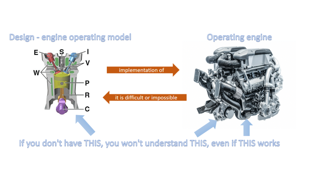
Design vs implementation
Introduction
In software development, design software refers to the process of defining the structure, components, and behaviour of a software system. In contrast, implementation software focuses on translating those designs into actual, executable code. Essentially, design is about planning and architecture, while implementation is about building and coding.
Here’s a more detailed breakdown:
Design Software:
- Purpose: To create a blueprint for the software, specifying its functionality, architecture, and user interface.
- Activities: Requirements gathering, system modelling (using diagrams like UML), database design, user interface design, and creating technical specifications.
- Focus: Problem-solving, high-level planning, and creating a clear vision of the software before coding begins.
- Output: Design documents, specifications, prototypes, and architectural diagrams.
Implementation Software:
- Purpose: To turn the design into a working, executable software product.
- Activities: Writing code in a specific programming language, unit testing, integration testing, and debugging.
- Focus: Coding, testing, and deploying the software based on the design specifications.
- Output: Source code, compiled binaries, and the deployed software application.
Disaster Response and Recovery Process in a Manufacturing Enterprise
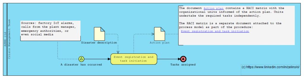
Scenario Title: Disaster Response and Recovery Process in a Manufacturing Enterprise
Description: This process is triggered when a manufacturing plant faces a natural disaster such as a flood, fire, or earthquake. The event may be detected via various sources — factory IoT alarms, calls from the plant manager, emergency authorities, or even social media. Once detected, the Crisis Management Team is activated, triggering multiple parallel response tracks: Human Safety Track: Evacuation, medical assistance, employee family coordination Business Continuity Track: Alternative sourcing, production rerouting, insurance claims Infrastructure & IT Track: Damage assessment, disaster recovery, data risk mitigation External Communication Track: Legal disclosures, PR statements, government reporting The process involves numerous asynchronous events, external parties, exception handling, and delayed subprocess closures like audits and legal resolutions
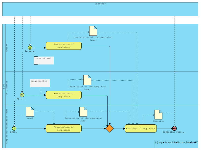
Process for managing customer complaints at a bank
Kolejne zadanie postawione na LinkedIn (LINK)
“Let’s imagine a process for managing customer complaints at a bank, where they can be received at the branch, on the customer line or directly by e-mail from the complaints management team. How can I illustrate this scenario with BPMN, taking into account the different entry points? Note that regardless of the entry point, the complaint must be forwarded to the complaints management team.”