Models and architecture
now browsing by category
The main category of my posts, my experience and research as well.
What is the difference between the requirements of the solution and the needs of the user?
Seven years ago (2015), I ended an article about requirements and traceability with the words: So the business requirements may be dozens. The required system services (use cases) in a large project may also be dozens. But hundreds or thousands of ?requirements? is an expression of losing control of the project scope? Here I would like to point out that a requirement (a system service) could be, for example, a VAT invoice produced in compliance with the regulations. The features of this invoice (list of fields) are not separate requirements, they are features (parameters, attributes) of a single requirement. No feature of the VAT invoice has any value on its own so it cannot be a separate use case, just as our requirement can be a car but its colour or automatic transmission are features of the car, it makes no sense to require ?red colour? without expecting a car (and how to justify that this colour supports the business objective). The use case for a car is the journey and not the insertion of the key into the ignition, because this is just one element of the scenario of starting a car journey.Source: Why is requirements tracing important in a project? – Jarosław Żeliński IT-ConsultingThere are publications about requirements, their management and implementation. There are applications available on the market to collect them and manage such a collection. And we are constantly confronted with their – requirements – ambiguity (Šenkýř & Kroha, 2019). It turns out that their importance becomes crucial for projects, also from a legal perspective (PZP and the concept of need defined in the recommendations of the Public Procurement Office). This time I will focus on the concepts of ‘requirement’ and ‘need’ in relation to the solution design.
Work vs. design vs. intellectual property in engineering
Another discussion I had on LinkedIn recently showed that intellectual property law is very difficult to assimilate, mainly because – due to its ‘immateriality’ – it escapes the intuitive and material manners of human perception of the world. This is overlaid by the coder’s conviction that, in principle, they are autonomous creators, and unfortunately, many lawyers also think so. The thing is that the coder is always the creator, but not always the designer. When the coder is not a designer, their works (source code) are dependent works on primary works, which are technical designs expressed, for example with the help of UML, mathematical formulae, algorithms. Then we expect coders, as developers, to do their craft brilliantly.Given that I often use purposeful and systemic interpretation of contracts and law in the expert reports I write, I have decided to describe here an ontological analysis of this area of engineering. The aim is to determine the meaning and range of definitions of terms commonly used in the field of intellectual property. I also hope to help you with this to make better software supply contracts.
Source: Creation vs. design vs. intellectual property in engineering – Jarosław Żeliński IT-Consulting.
ICONIX as an object-oriented, agile software design process using UML notation
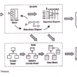
The fact that ICONIX, as a process, is relatively rarely used (this has been changing over the last few years, however), is rooted in the fact that, first and foremost, it requires an understanding of the component-oriented architecture process, it also requires knowledge and understanding of the concept of hexagonal architecture and the associated MVC pattern. Requires knowledge and understanding of many other object-oriented design patterns, requires, above all, abstract thinking and modelling (UML) skills. It requires an understanding that z coding must be preceded by design, because ‘designing’ in code is the least effective form of design (Börger, 2018).The process is also supported by the division into analysis and design and implementation stages (see above diagram: Structure of project roles and products in the ICONIX process). ICONIX is sometimes wrongly associated with a “heavy” software development process such as the Rational Unified Process (which I have hardly written about on my blog). The reason ICONIX is rarely used, is also that, unfortunately, the world was, already in the 1990s, heavily “spoiled” by C++ and Java (architectures built on cascades of inheritance). These are often heavy, monolithic frameworks based on a relational data model, where there is no strict separation between domain logic and environment (MVC). Java is still one of the most costly and least effective application development methods. The EJB framework is to this day described as the source of an object-oriented design anti-pattern called the ‘anemic domain model’. However, the growing developer interest in the C4 model over the last few years shows that analysis and modelling are needed and quietly entering through the back door….The fact that ICONIX, as a process, is relatively rarely used (this has been changing over the last few years, however), is rooted in the fact that, first and foremost, it requires an understanding of the component-oriented architecture process, it also requires knowledge and understanding of the concept of hexagonal architecture and the associated MVC pattern. Requires knowledge and understanding of many other object-oriented design patterns, requires, above all, abstract thinking and modelling (UML) skills. It requires an understanding that z coding must be preceded by design, because ‘designing’ in code is the least effective form of design (Börger, 2018).The process is also supported by the division into analysis and design and implementation stages (see above diagram: Structure of project roles and products in the ICONIX process). ICONIX is sometimes wrongly associated with a “heavy” software development process such as the Rational Unified Process (which I have hardly written about on my blog). The reason ICONIX is rarely used, is also that, unfortunately, the world was, already in the 1990s, heavily “spoiled” by C++ and Java (architectures built on cascades of inheritance). These are often heavy, monolithic frameworks based on a relational data model, where there is no strict separation between domain logic and environment (MVC). Java is still one of the most costly and least effective application development methods. The EJB framework is to this day described as the source of an object-oriented design anti-pattern called the ‘anemic domain model’. However, the growing developer interest in the C4 model over the last few years shows that analysis and modelling are needed and quietly entering through the back door….
Source: ICONIX jako obiektowo zorientowany, zwinny proces projektowania oprogramowania z użyciem notacji UML – Jarosław Żeliński IT-Consulting
True Engineering

A few days ago I was talking about the border between requirements analysis and engineering with Tom Gilb. The conclusion is: that we have to separate the requirements stage and the engineering stage. A huge thank you to Karolina Zmitrowicz for organizing this meeting.
UML model and stereotypes as icons
Someone will ask: why all this? The thing is that managing presentation graphics (model consistency, tracing, etc.) is practically impossible: any change requires interference with block diagrams and laborious reinsertion into the analysis report (I wrote about this in an article about CASE tools). Such graphics are not transferable between tools other than as uneditable bitmaps. However, if someone feels that block diagrams expressed in more ‘friendly’ symbols add value to the project, they can do so. The UML provides for this and many tools allow it (I used Visual-Paradigm).
Source: UML model and stereotypes as icons – Jarosław Żeliński IT-Consulting.
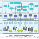
Information architecture, information system vs. information technology in the organisation
There are also simple and obvious conclusions:
- there is no point in designing an “information system” without fully understanding (i.e. also documenting) the “information system, “
- there is no point in placing the elements of the “information system” on “information system” models (e.g. There is no point in putting the “information system” elements on “information system” models (e.g. symbols representing software on BPMN models)
- the relationships between the “information system” elements and the “information system” elements are described with the help of the traceability matrix
- Developing the requirements for the “information system” is about identifying the “business needs” and developing the logic of operation and architecture of the “information system” on their basis (MBSE, MDD), and not on collecting mythical “user requirements”, who in fact have no idea about “information systems”, but know very well if and when they need help in the business processes being implemented this is why methods based on designing an “information system” on the basis of interviews (workshops) with future users are doomed to failure from the outset (because even if something sensible is finally created, it will take a lot of trial-and-error work)
- One thing we have known for years: one of the most damaging theses in IT is the one saying that a document is a report from a database.
Diagrams in UML notation
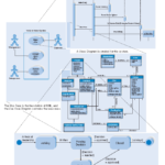

UML diagrams and the way they are used, since the very beginning of this notation, have aroused emotions and waves of conflicting comments. The reason for this is the high level of abstraction of the analysis stage and modelling as a discipline, and the fairly widespread misunderstanding of the essence of this notation. This is compounded by the huge difference between what we call analysis and object-oriented design (OOAD) and object-oriented programming languages (OOP).UML notation is mistakenly treated by many people as just another set of symbols for creating illustrations. Most developers I know feel that these diagrams do nothing to help them, and they are generally right, because the quality and content of much of the documentation produced with UML, is poor, and such documentation is actually useless to the software vendor.
Source: Diagramy w notacji UML – Jarosław Żeliński IT-Consulting
Value-stream mapping i.e. the value stream a company creates when creating its product
The acronym VSM has also started to appear in software engineering for some time now, but it has an old pedigree of more than 30 years. Value-stream Mapping (VSM), known for 30 years, more recently also as material- and information-flow mapping. It is a method with its origins in Lean Management, used to analyse the current state and design the future state for the series of events that lead a product or service from order to delivery to the customer.
Source: Value-stream mapping czyli strumień wartości jaki wytwarza firma tworząc swój produkt – Jarosław Żeliński IT-Consulting
What are tests and who tests what
Testing is checking, and here we have (should have) a clear division between the checker and the checked. It is typical of the IT market to tell customers that they have no competence in analysis, testing, design, that all this will be done by the software supplier. Thus, the following are ordered from the same, single, software supplier: business analysis, requirements analysis, design, implementation, writing acceptance tests and testing. An entity like the Purchaser in essence just watches, and pays as much as the suppliers want (T&M projects are out of control). In effect, the checker and checked are the same entity. Does this make sense?
Source: Czym są testy oraz kto i co testuje – Jarosław Żeliński IT-Consulting
SysML – a few words about
In this place, I have been collecting some speaks about the SysML language. It is origin from UML (it is a UML profile). SysML is the main MBSE method we use for documenting mechatronics models.