BPMN
now browsing by tag
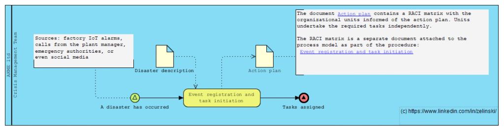
Disaster Response and Recovery Process in a Manufacturing Enterprise
Scenario Title: Disaster Response and Recovery Process in a Manufacturing Enterprise
Description: This process is triggered when a manufacturing plant faces a natural disaster such as a flood, fire, or earthquake. The event may be detected via various sources — factory IoT alarms, calls from the plant manager, emergency authorities, or even social media. Once detected, the Crisis Management Team is activated, triggering multiple parallel response tracks: Human Safety Track: Evacuation, medical assistance, employee family coordination Business Continuity Track: Alternative sourcing, production rerouting, insurance claims Infrastructure & IT Track: Damage assessment, disaster recovery, data risk mitigation External Communication Track: Legal disclosures, PR statements, government reporting The process involves numerous asynchronous events, external parties, exception handling, and delayed subprocess closures like audits and legal resolutions
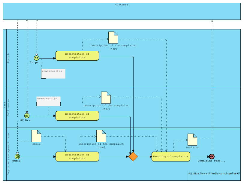
Process for managing customer complaints at a bank
Kolejne zadanie postawione na LinkedIn (LINK)
“Let’s imagine a process for managing customer complaints at a bank, where they can be received at the branch, on the customer line or directly by e-mail from the complaints management team. How can I illustrate this scenario with BPMN, taking into account the different entry points? Note that regardless of the entry point, the complaint must be forwarded to the complaints management team.”
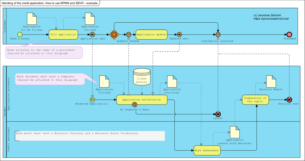
Handling of the credit application. How to use BPMN and SBVR – example.
A common problem in companies, both very small and very large, is the lack of full knowledge of how the company really works. The consequence is the unpredictability of the consequences of decisions taken.
Innym negatywnym efektem tego braku wiedzy jest trudność w zawieraniu umów i wdrażanie do pracy nowych pracowników.
The solution to both of these problems is a correctly executed business model, the backbone of which is business process maps, associated procedures, business rules and document templates. A correctly developed model allows you to familiarise yourself with everything that affects the business quickly. It also allows everyone to understand how the business works.
Below is an example of such a model: the business process model.
Mechanism of operation vs. system model
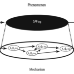
Most often in the course of analysis we use the term model, less often mechanism. The thing is that the term mechanism appears when we want to explain something, e.g. “the mechanism of generating a discount on an invoice”. The thing is that the term mechanism appears when we want to explain something, e.g. “the mechanism for generating a discount on an invoice”. But here beware! A model (block diagrams, formulae, etc.) is documentation, a copyrighted description. The mechanism is what we understood by reading these documentation (model), because the mechanism is protected know-how. The content of the application to the Patent Office is the model (description), but what we patent is the mechanism invented/developed.
Source: Mechanism of operation vs. system model – Jarosław Żeliński IT-Consulting
Synthesis of MOF, MDA, PIM, MVC, and BCE Notations and Patterns

Exactly one year ago my first paper in US ? (see liflet)
Abstract
Publications, including academic handbooks, contain numerous inconsistencies in the descriptions of applications of architectural methods and patterns hidden under the abbreviations such as MOF, MDA, PIM, MVC, BCE. An efficient analysis and the following software design, particularly when we are speaking of projects realized in large teams, requires standardization of the production process and the applied patterns and frameworks. This study attempted to sort out the system of notations describing this process and used to describe architectural patterns. Analysis of key notations?MOF and MDA, patterns MVC and BCE?was carried out, and a consistent system combining them into a whole was created.Chapter Preview Top
Background
In this study, Object Management Group notation systems have been used. MOF (Meta Object Facility) specification describes three abstraction levels: M1, M2, M3 and level M0 that is real items (OMG MOF, 2016). M0 is a real system, M1 level is abstraction of the items of this system (its model). Level M2 comprises of relationships between classes of these objects (names of their sets) that is system metamodel. M3 level is a meta-metamodel describing the modeling method with the use of named elements with specified semantics and syntactic.
The analysis and design process is based on the MDA (Model Driven Architecture) specifications. This process has three phases understood as creation of subsequent models: CIM (Computation Independent Model), PIM (Platform Independent Model), PSM (Platform Specific Model) and code creation phase. The CIM model is documented with the use of BPMN (Business Process Model and Notation) (OMG BPMN, 2013) and SBVR notation (Semantic of Business Vocabulary and Rules) (OMG SBVR, 2017). These are, respectively: business process models and notation models and business rules. PIM and PSM models are documented with the use of UML notation (Unified Modeling Language) (OMG UML, 2017).
Between CIM and PIM models, determination of the list of application services (system reactions) occurs, whose realization mechanism is described by PIM model. The standard pattern used for modeling application architecture is MVC pattern. Component Model of this pattern is modeled with the use of the BCE architectural pattern.
Semiotics vs. UML
Semiotics, as a science dealing with symbols and their meanings, provides us with the tool enabling determination of relationships between an object (thing), its name (expression) and definition of notation represented by the name (or sign, meaning). These relationships are referred to as the semiotic triangle. Figure 1 represents this triangle on the left (OMG SBVR, 2017).
The UML notation (OMG UML, 2017) operates instance classifier and class notations. To the right, Figure 1 demonstrates an equivalent to semiotic triangle expressed with those terms.
The UML notation further operates the general structure notation, which is the content of each correct UML diagram. Structures may express a conceptual model (Namespace) or model (also metamodel) of system architecture (e.g. software) in the form of a chart (Architecture).
Synthesis of MOF, MDA, PIM, MVC, and BCE Notations and Patterns

Jaroslaw Zelinski (Independent Researcher)
Source Title: Applications and Approaches to Object-Oriented Software Design: Emerging Research and OpportunitiesCopyright: ? 2020 |Pages: 12DOI: 10.4018/978-1-7998-2142-7.ch003
Business continuity management – how to model it

Business Continuity Management (BCM) projects are really difficult . The main reason is the system complexity: many documents, many tasks, many processes, many associations between all of them. Each task connected to one or more business application. Each documents stored in different database. The applications are integrated. Everything works like one chain ? but one broken link can crash everything .
How we can managing risks? We can create Business Architecture model and expand this up to Enterprise Architecture, as a model for trace process, data, IT system and infrastructure.
How we prepare Enterprise Architecture model? Simple version: prepare business model :
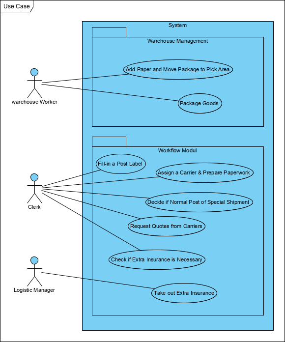
Transform this to use case model (application services) :
Build matrix for trace mapping control :
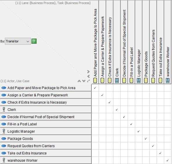
Trace (map) use case to software components :
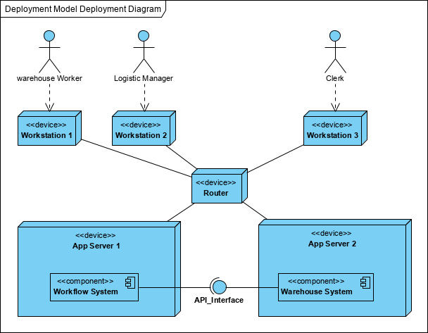
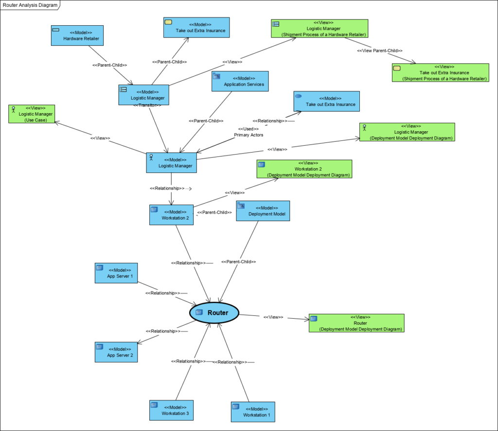
We have completed model, we can do impact analysis, e.g. what happens and where, when the Ruter go down:
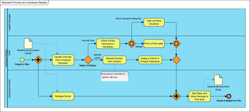
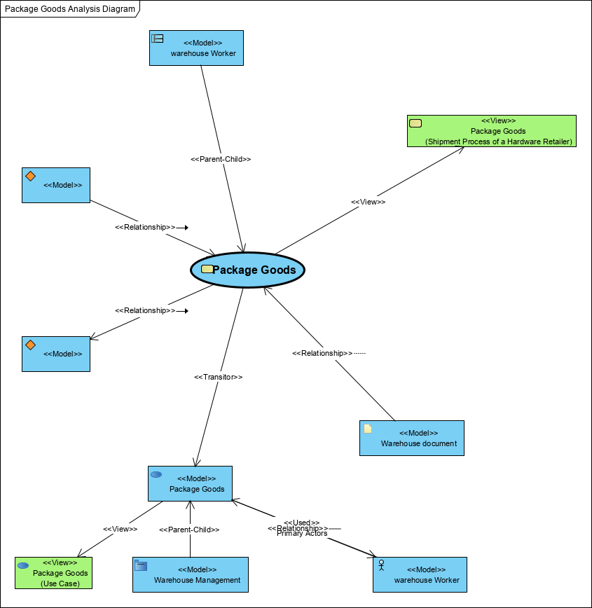
Sometimes we ask: what does the possibility of carrying out the Package Goods task depend on?
How can we do this and what tools do we need? Welcome in my courses, hire me …